
If you want to know about the installation process of a VRF system, then you are in the right place. As a professional, I am explaining everything to you. In the future, if you want to start your career in HVAC or you are interested in installing a VRF system in your place, this will be helpful for you.
After you get the project design, you need to prepare the budget/BOQ. Then you need to deliver all materials and tools. Before you start the work, you need to get design approval from the client.
Installation process of VRF:
– Marking work
– Indoor unit hanging
– Copper pipe support & hanging work
– Drain pipe support & hanging work
– Duct fabrication & hanging work
– Air terminal installation work
– Communication cable pulling, thermostat cable pulling & thermostat installing
– Pressure test & insulation
– Vacuuming and commissioning
Marking work:
At first, you must complete the marking work. It’s mandatory because after the marking work, it’s easy to complete the support work perfectly. This helps you know where to place the unifix and threaded rod. If the project requires wall punching due to a particular work issue and there isn’t enough space, you must mark that part so the wall punching work can be done perfectly.
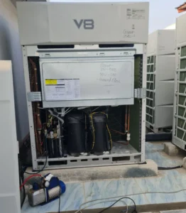
Indoor unit hanging:
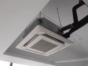
After completing the marking work, we start the indoor unit hanging work. Normally, for 1 or 4kw indoor unit hanging, we use a 10mm threaded rod, unifix, etc and for more heavy indoor unit we use isolator box, thread rod etc. depending on the indoor unit’s weight.
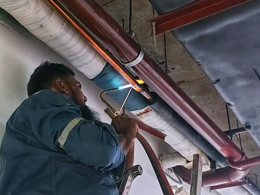
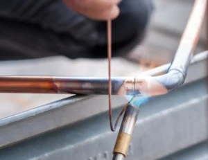
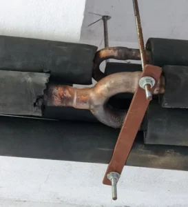
Copper pipe support & hanging work:
After completing the copper support work, we start the copper welding with copper elbows, reducers, and Y joints/refnet joints. After completing the copper branch work, we connect the machine. Each machine has two copper pipes: one for liquid refrigerant supply to the evaporator of the indoor unit, and the other for gas refrigerant return to the compressor of the outdoor unit. For welding, we use brazing rods.
Drain pipe support & hanging work:
For drain work, we use straight or flexible PVC pipe. Whether it’s drain or copper, you must complete the support work. For drain pipe connections, we use PVC glue, elbows, reducers, etc. This refrigerant cycle produces unnecessary water, which needs to be directed to the toilet or, as per the client’s requirement, through a drain riser. After completing the drain pipe work, we need to ensure the insulation is done and also cover the insulated pipe with 2” tape for better looks and longevity.
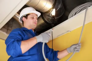
Duct fabrication & hanging work:
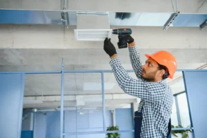
When you have a fresh air unit and fresh air supply in your floor, you must do duct work. It takes more time than VRF work. Unlike pipe work, if you want to work with factory-made duct, you need to order the duct first as per design and site requirements. Alternatively, it is possible to make the duct on-site as per requirements. We use different qualities of GP sheet depending on the width of the duct. If the duct width is 0 to 750mm, we use 24 gauge GP sheet; if the width is 750mm to 1300mm, we use 22 gauge GP sheet; and if the duct width is bigger than 1300mm, we use 20 gauge GP sheet.
There are many types of ductwork such as,
- straight duct,
- offset duct,
- elbow duct,
- reducer duct,
- transition duct,
- tee duct,
- circular duct,
- oval duct.
Also, there are many types of duct fabric, like GP sheet(GI & SS), fabric duct, flexible duct, etc.
As mentioned earlier, you also need to work on support. After the duct making work, complete the insulation and hanging work. If required, connect the duct with VCD.
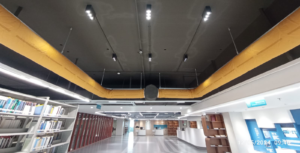
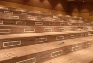
Air terminal installation work:
Once you complete the duct work, you need to install the air terminal. Install liner grilles, diffusers, and round diffusers as per design. We install these grilles on the ceiling or wall, so for ceiling area grille installation depends on the ceiling work.
When you have fresh air supply and exhaust air lines in your system, you need to install fresh air and exhaust fans.
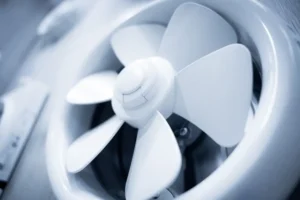
Outside the building, install louvers in front of the outside fresh air and exhaust fans to protect the duct from outside rainwater.
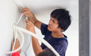
Communication Cable, Thermostat Cable pulling & Thermostat installing:
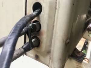
Communication Cable:
Once you complete the indoor unit hanging, outdoor installation in base, copper, and drain works, you can start the communication cable pulling work. In the system, you need to connect all indoor units with the communication cable. If your system has two outdoor units, the communication cable will connect with the first outdoor unit and then with the second outdoor unit. The first one is the master outdoor unit and the second one is the slave.
Thermostat cable pulling and installation:
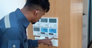
As we know In cassette-type indoor units, we control the temperature with a remote. But in duct-type indoor units, we need a thermostat to control the temperature. First, connect the thermostat with the indoor unit and complete the cable pulling work according to the thermostat location. The location of the thermostat depends on the client’s preference.
There are several types of thermostat cables, like 2-core, 3-core, 5-core, and 7-core. You need to select the thermostat cable based on your indoor unit and thermostat. If your indoor unit and thermostat require a 5-core cable, you must use a 5-core cable for your system.
After installing the thermostat, connect it with the cable. The thermostat will work with the E.E.V (Electronic Expansion Valve) and by using thermostat you can control the refrigerant flow of your indoor unit.
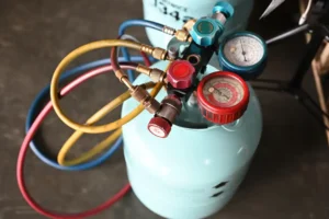
Pressure test and leakage issue:
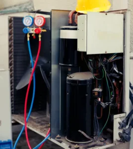
This is the most sensitive task in VRF, we use nitrogen gas for pressure test work. Before refrigerant charge you must do the pressure test. Otherwise, it’s not possible to fix the leakage issue.
Leakage issue: There will be several reasons behind leakage issues, Like
*The low-quality installation process. Maximum time the vendors continue the work with inexperienced workers, this is the most common reason behind this.
* sometimes the contractor wants to complete the work so fast resulting in improper welding.
– Physical damage to the copper pipe.
– VRF systems vibrate slightly due to high refrigerant pressure, which can cause leakage if the welding is of low quality.
We use nitrogen gas for the pressure test, usually at 300 psi. If you see the pressure drop from 300 psi to 250 psi, 200 psi, or less, it means there is a leakage issue. You need to find and fix the leakage. It can take 2 to 4 days, depending on the system length or how critical the pipe work is.
Example: In 2023, I faced a horrible experience with a leakage issue. It was a Midea 500-Ton VRF system in a shopping mall. We proceeded with copper installation work with the insulation, but only the spaces where we connected two copper pipes, or where there were copper Y joints and elbows, remained uninsulated for welding purposes.
After completing the pressure test, we finished the remaining insulation, which is a regular process. However, in that project, we spent four days trying to find the leakage in the system without success. We then thought that there might be a leakage somewhere in the middle of the copper pipe. So, we removed all the insulation from the copper pipes and began the leakage-finding process again. On the second day, we found it. During this period, we faced significant pressure from our client, and it took an additional eight days to meet our work schedule.
This issue happened due to low-quality materials. Make sure you choose the perfect materials for your project.
During this leakage finding and fixing work, your project duration may be extended, and you will face client pressure. To avoid this, monitor the vendor/contractor work quality, especially the welding work.
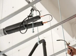
Insulation:
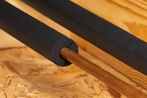
Before the pressure test is complete, we can’t finish the insulation work. If we do that, we would need to remove the insulation to repair the leakage. Insulation saves your system from energy loss, pipe sweating issues, maintains unit performance, and protects against high temperatures.
After completing the insulation work, use 2-inch wrapping tape to cover the insulated pipe for a long-lasting and good appearance.
Vacuuming and commissioning:
Once you have completed the pressure test, you need to remove the nitrogen gas from your system. That’s why you need to perform a vacuum. After vacuuming, charge the refrigerant into your system.
To determine how much refrigerant your system needs, use the following example:
For a system with a 12-meter copper pipe and the pipe diameter is 0.01:
Volume of pipe (m3) =3.1416{0.01(diameter of the pipe)/2}^2*12(Because your system has 12m pipe)
=0.000942m3
*Density of 410A Gas = 48.9 kg/m3
*Refrigerant charge (KG) =0.000942*48.9
=0.0461 KG
By using this formula, you can determine how much refrigerant is required for your system.
After successfully completing the refrigerant charging, you can commission the system and, when the project is successfully commissioned, complete the handover process.