
There are a lot of people who want to know about the VRF system. Maybe they are studying it or are interested in starting their career in the HVAC industry. Here, I am explaining everything about VRF from my own experience. When I started my career in the HVAC industry, my first project was a 400TR LG VRF project where I faced many problems. But after handing over that project, I understood it very well. Since then, I have never looked back. I believe that by the end of reading this blog, the VRF system will be as clear as water to you.
What is VRF/ VRV System in HVAC:
VRF means Variable Refrigerant Flow. In VRF, unlike the Split/Unitary system, you can use several indoor units in one system. So according to your requirements and indoor unit capacity, the refrigerant flow varies in each indoor unit. That’s why it’s called a VRF system.
VRF can provide both heat and cooling as per your requirements. It uses common refrigerants like R410A. You get many options to customize your system, you can install it as per your design.
Although it costs more than the split system, it provides more value, such as better efficiency, better life expectancy, and also looks great compared to the split system.
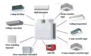
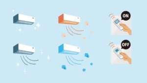
There are different types of indoor units used in VRF/VRV systems, like 4-way or 2-way cassette-type indoor units, wall-mounted indoor units, duct-type indoor units, etc.
Example of Refrigeration cycle/ unitary system:
To understand the VRF system, you need to have an idea of the refrigeration cycle or unitary system (regular AC). Let’s talk about the unitary system. As we know, in a VRF system, several indoor units can connect with a single outdoor unit, but with a unitary system, one indoor unit can be connected with only one outdoor unit.
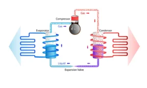
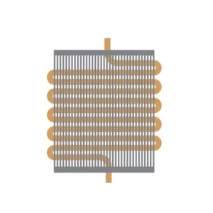
As you can see in the picture, there are two heat exchangers. In the indoor unit, chilled liquid refrigerant absorbs the heat from room temperature, and the liquid refrigerant converts to low-pressure gas after absorbing heat from the room temperature. After that, the compressor compresses this low-pressure gas, and it turns into super-heated gas. This super-heated gas goes to the heat exchanger (condenser) of the outdoor unit, where it loses power (sensible heat converts to latent heat) and becomes liquid. After that, due to the expansion valve, the liquid refrigerant goes to the IDU and absorbs the heat from the room temperature. This is how it works with a single indoor unit and outdoor unit.
Working Principal Of VRF/VRV (E.E.V, Evaporator, Accumulator, Compressor, Condenser):
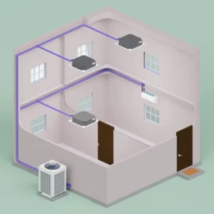
In the first picture, you can see a single outdoor unit connected with a single indoor unit. What if we develop this system a bit, where multiple indoor units can connect with a single outdoor unit? In the VRF system, the liquid refrigerant will go to the evaporator, and it will evaporate the liquid refrigerant, converting it into a gas-liquid form. In the accumulator, this liquid-gas form will convert completely into gas form, and this low-pressure gas will go to the compressor and become high-pressure super-heated gas. This high-pressure super-heated gas goes to the condenser (heat exchanger) of the outdoor unit, where the refrigerant is converted to liquid by condensing. After that, the expansion valve will expand this liquid, and it will go to the evaporator (heat exchanger) of the indoor unit. This is how it works. In the picture below, you can see an example of VRF system where two indoor units are connected with a single outdoor unit.
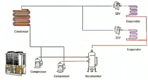
So here, from the outdoor unit, chilled liquid refrigerant will reach the first indoor unit and, after that, by a different route, it will reach the second indoor unit. Before this, in the unitary system, we could control only a single room temperature using it. But here, as you can see, we can use two ACs and control two room temperatures. In the unitary system, it was a closed loop, and there were no Y joint/refnet joints. But now we make a different route by using the Y joint/refnet joint and connect another indoor unit (AC).
Now two individual indoor units are connected with one outdoor unit, and both indoor units can have different requirements (depending on your usage). Assume the first indoor unit capacity is 1 Ton and the second indoor unit capacity is 2 Tons. Again, the 2-ton indoor unit may have to run at 1.5 tons as per the requirement because the inside temperature may be set high. Now how to control it?
In the unitary system, there was only one indoor unit, so the refrigerant flow would be reduced if the compressor turned slowly.
However, if there are several indoor units in a system like VRF, the refrigerant requirement in each indoor unit will be different according to the indoor unit capacity. For example, here there are two indoor units; the first one has 1-ton capacity and the second indoor unit has 2-ton capacity. Naturally, a 2-ton indoor unit will need more refrigerant than a 1-ton indoor unit. Now suppose that the temperature of the 1-ton indoor unit is kept at 21 degrees Celsius inside the room and the temperature of the 2-ton indoor unit is kept at 27 degrees Celsius inside the room. Here, the first indoor unit requirement is 1 ton, but the second indoor unit requirement is 1.5 tons because in the 2nd indoor unit, the flow of refrigerant will be less because the room requirement is lower. That means in the VRF system, refrigerant flow in the indoor unit varies based on your required temperature in the room. We use a sensor or expansion valve to control it. We call it EEV or Electronic Expansion Valve. This electronic expansion valve controls the indoor unit refrigerant flow depending on the thermostat. It controls the refrigerant flow by opening and closing the needle valve of the EEV.
E.E.V:
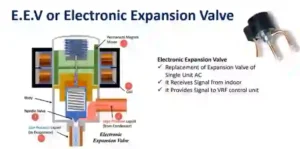
Now if we run the indoor unit of 2 TR capacity at high temperature, that means the requirement is low. So the needle valve will be half-closed or will be closed as per the requirement, and pressure will be created on both sides of the needle valve. The data of this pressure creation will go to the compressor, which will then adjust its own volume as needed.
Evaporator:
The indoor unit does not bring outside air into your space. It repeatedly cools the indoor air.
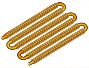
The evaporator is a heat exchanger of the indoor unit. As we know, liquid refrigerant goes to the evaporator of the indoor unit. Here it absorbs the heat from room air and makes your place cold. During this heat exchange process, the liquid refrigerant converts to gas by absorbing room temperature. Actually, in the VRF system, after the evaporation process, some liquid remains with the gas. That’s why this gas and liquid form of refrigerant goes to the accumulator, where it completely converts to gas form.
Accumulator:
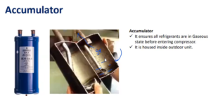
Now here the refrigerant first goes to the IDU and then it goes back to the compressor. But in the unitary system, when there was only one IDU with ODU, it was confirmed that after heat exchange in the IDU, liquid refrigerant would convert to gas and go to the compressor.
But in the VRF system, liquid refrigerant after heat exchange in the IDU will not be completely converted to gas; some of it remains in liquid state. This gas-liquid refrigerant goes to the accumulator, where it is completely converted into gas. Later, this low-pressure gas from the accumulator is compressed in the compressor and becomes superheated gas.
Compressor:
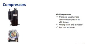
An ODU can have multiple compressors. The first compressor will have an internal loop to recirculate the lubricant oil and then we can take the refrigerant to the second compressor. The second compressor will also have an internal loop to circulate the internal lubricant. Refrigerant gas will come out from the compressor at high pressure and go to the heat exchanger of the ODU. One of these two compressors will be called master and the other one is slave. Simply put, one will be on primarily and the other one secondarily. The primary compressor will be on to maintain the flow on this floor. When the primary compressor is saturated, then the second compressor will be on; when the second compressor is saturated, if there are more compressors, they will be on.
Condenser:
From the compressor, the high-pressure refrigerant will go to the heat exchanger (condenser) of the ODU. In this process, the superheated refrigerant gas is cooled through heat (exchange/Condenser). After that, it passes through the expansion valve, where it transforms into chilled liquid refrigerant. This chilled liquid refrigerant then goes to the evaporator & makes your room comfortable. This is how the process continues.
In VRF, the refrigerant flow varies according to the requirement of each machine, hence it is called VRF. Another name for VRF (Variable Refrigerant Flow) is VRV (Variable Refrigerant Volume). Initially, when the Japanese invented it, they patented it as VRV. Later, when the Europeans copied it, they named it VRF to avoid patent issues. There is no more difference between VRV and VRF. The cycle we have talked about so far looks a lot like this.
Here, the accumulator, compressor, and condenser/heat exchanger are part of the ODU unit, and the EEV (Electronic Expansion Valve) and evaporator are part of the indoor unit.
Now I have some questions for you:
why is IDU (Indoor unit) called Evaporator?
= IDU is called evaporator because refrigerant evaporates here.
Why do we call ODU condenser?
= Because here the refrigerant is converted to liquefied by condensing.
Y Joint/ Refnet Joint/ Copper Branch:
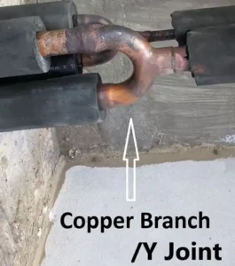
As we know, in VRF systems, several indoor units operate on a single system. Suppose there are 10 indoor units in one system, but only two copper pipes come out from the outdoor unit. Without Y joints/refnet joints, it’s not possible to complete the copper connection work with the indoor units. For 10 indoor units, you require 9 Y joints/refnet joints, because for the last indoor unit’s copper work, you don’t need a Y joint/refnet joint. You can complete the pipe connection by using elbows.
VRF installation process:
In the VRF installation process, there are several steps that I am explaining to you:
* Marking work
* Indoor unit hanging
* Copper pipe support and hanging work
* Drain pipe support and hanging work
* Duct fabrication and hanging work
* Air terminal installation
* Pressure test
* Insulation work
* Communication cable & thermostat cable pulling and connection, and thermostat installation work
* Vacuuming and commissioning
For more details, read my blog on “the installation process of the VRF system”
Every VRF project shares similarities, the most challenging thing is addressing leakage issues in a system. Here I am describing the pressure testing, leakage detection and insulation work which is required to ensuring a flawless system.
Pressure test and Leakage detection:
This is the most sensitive task in VRF. Before refrigerant charge you must do the pressure test. There could be several reasons behind leakage, Like
- The low-quality installation process. Maximum time the vendors continue the work with inexperienced workers, this is the most common reason behind this.
- And sometimes they want to complete the work so fast and because of this they don’t complete the welding work properly.
- If the copper pipe got physically damaged by something.
- When the VRF system is operational, it vibrates slightly due to the high pressure of refrigerant. If there is low-quality welding at the elbow and Y joints, a leakage issue can happen.
We use nitrogen gas for pressure testing.
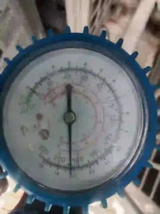
Normally, we apply 250/300 psi for the pressure test. If after some time you notice that the pressure has dropped from 300 psi to 250 psi, 200 psi, or lower, it means your system has a leakage issue because the pressure is escaping due to the leak. This is when you need to find the leak and fix it. It can take 2 to 4 days, or more, to find the leakage issue, depending on the system length or how complex the pipework is.
During the leakage finding and fixing process, your project duration may extend, leading to pressure from the client. To avoid this, you need to monitor the vendor/contractor’s work quality, especially the welding work.
Insulation:
Before the pressure test is done, the insulation work cannot be completed. If you do, you will have to remove the insulation to repair any leakage. Insulation saves your system from energy loss, pipe sweating issues, and maintains unit performance, protecting you from high temperatures. After completing the insulation work, you need to use 2-inch wrapping tape to cover the insulated pipe. This will make it long-lasting and visually appealing.
Vacuuming, Refrigerant charge and commissioning:
Once you done the pressure test then you must need to get out the nitrogen gas from your system. That’s why you need to vacuum your system. After vacuuming, you need to charge the refrigerant into your system. Now, the question is, how do you know how much refrigerant your system would need?
Here’s an example for you: Suppose your system has a 12-meter copper pipe, and the pipe diameter is 0.01.
12m copper pipe refrigerant charge, diameter of the pipe 0.01:
*Volume of pipe (m3) =3.1416*{0.01(diameter of the pipe)/2}^2*12(Because your system has 12m pipe)
=0.000942m3
*Density of 410A Gas = 48.9 kg/m3
*Refrigerant charge (KG) =0.000942*48.9
=0.0461 KG
By Using this formula, you can easily find out how much refrigerant is required for your system.
After completing the refrigerant charging, you can commission the system. When you successfully commission the project, you can complete the handover process.
VRF/VRV vs Split AC:
VRF/VRV is very efficient compared to the split system. Split AC consumes 1.2KW/Ton & VRF/VRV consumes 0.8KW/Ton, so I hope the difference is clearer to you. Although it cost more then the Split AC. But its life expectancy is 15 years, while the split AC life expectancy is 10 years.
Solution | Electricity consumption | Life expectancy | Investing | Project duration |
VRF/VRV | 0.8KW/Ton | 15 years | Average | Short |
Split AC | 1.2KW/Ton | 10 years | Low | Shortest |
Space & looks issue:
Split AC:
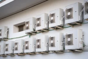
In a split system, several indoor units cannot connect with a single outdoor unit. So, if your home has three rooms and you want to install individual split AC in each room, you need enough space to install the outdoor unit. Alternatively, you can hang those outdoor units outside the building, but it looks awful.
In a commercial space, you will need many indoor units due to the large space and more members in the space. In this condition, if you choose a split system, your building will look so ugly because of the numerous outdoor units.
VRF system:
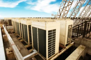
In cities like Dubai, you see many beautiful buildings where split ACs are not used. with VRF systems, you don’t face this kind of issue. In a VRF system, 60 to 64 indoor units can be operated with a single outdoor unit. Modern buildings often have separate spaces for outdoor unit installation; if your building doesn’t have enough space to install the outdoor unit, you can install it on the rooftop or hang it outside the building. The benefit of VRF is that you don’t need to install as many outdoor units as in a split system, so your building looks great and smart.
Customization & control of your VRF system:
You can customize a lot according to your requirements. Unlike split ACs, you can use multiple indoor units in one system. You can select cassette type IDU (Indoor Unit), duct type, FCU, etc. The complete work will be done according to your design. Suppose you don’t have enough space on the floor to install the outdoor unit; you can easily install it on the rooftop and then connect it to the floor using copper risers. During the installation process, if needed, you can change the pipe rotation or indoor location.
You also have many options to control your room temperature. For duct-type indoor units, you should use a thermostat; for cassette-type indoor units, you can control them with a remote. You can also use CCM to control the whole system at once. Another way to control your VRF system is by using a Wi-Fi control system, allowing you to control your indoor units with your smart phone.
VRF for residential & commercial space:
VRF is most suitable for commercial spaces and is also good for residential projects like bungalows. As a project coordinator, I have worked on many commercial and residential projects. Honestly, if you understand the VRF working principle and installation process, it doesn’t matter whether it is commercial or residential. The whole process is the same.
Commercial:

If your commercial space don’t have enough space on your floor, you can install the outdoor unit on the rooftop area. After that, with the copper riser, you can easily connect it to the floor and complete the pipe work, though it costs more due to the extra copper pipe work. If you have a separate space for installing the outdoor unit on the floor, you can complete the usual copper work. Also, when you have fresh air indoor units or fresh air duct work on your floor, you must complete the duct support, making, and hanging work with insulation. After completing all this work, you need to install the liner grille, diffuser, and, for the fresh air fan, you need to install the outside louver to protect your duct from rainwater.
Residential:
In residential projects, I prefer to install the outdoor unit in the rooftop area because you gain extra space in your home. If the house has a swimming pool area and gym, I prefer to install an RTU machine on the rooftop for fresh air supply.
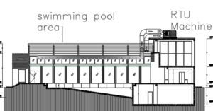
This is one of my ongoing residential projects. As you can see in the design, the Rooftop Unit (RTU) provides fresh air to the swimming pool area, and all the outdoor units are also installed on the rooftop area. There are also duct risers (fresh air and exhaust) for the basement fresh air supply.
Noise:

In a VRF system, you will not experience any noise issues in the indoor area. It’s very comfortable and eco-friendly. If there is any sound issue with the indoor unit, it means there is a problem with the fan motor, which is a maintenance issue. However, noise may occur in the outdoor unit area due to the blower fan, but since it is outside or on the rooftop, it’s not an issue at all.
Maintenance:
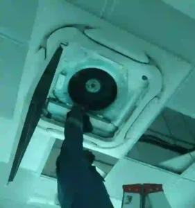
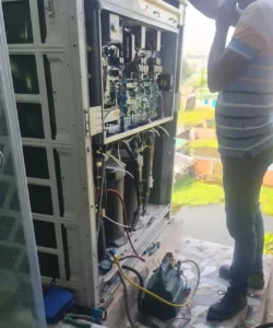
VRF systems are more efficient than unitary/split systems. However, the maintenance cost of VRF is higher than that of split systems. Many technical issues can occur in VRF systems, such as sound issues due to fan motor problems, water level sensor issues, PCB problems, etc. But it’s easy to maintain these issues using the service door.
If you find any leakage in a running system, that is the most difficult task to handle because it’s very hard to find the leakage area in the system. You need to remove the insulation and check all the pipes with a pressure test. It’s very time-consuming work.